
Dimensionally Accurate 3D Printing: A Guide to Print Parts that Fit
- Nathan Griese
- Apr 7
- 5 min read
Introduction: Why Dimensionally Accurate 3D Printing Matters
Dimensionally accurate 3D printing is critical for creating parts that fit together, function as designed, and meet engineering standards. Whether producing jigs, fixtures, or end-use components, tolerance stack-ups and dimensional variation can compromise a product's performance. Achieving precision involves more than just hitting "print." It requires calibrating your printer's axes, compensating for thermal contraction, and designing with fit and tolerances in mind.
For professionals and hobbyists alike, knowing how to improve 3D print tolerancing and fitment allows you to move beyond prototypes and into real-world applications. In this article, we explore how to calibrate your printer for dimensional accuracy, how material shrinkage affects results, and how to use CAD and GD&T principles to ensure parts fit correctly.
How to Calibrate a 3D Printer for Dimensional Accuracy
Calibrating your 3D printer's X, Y, and Z axes is the first step toward dimensionally accurate 3D printing. Even small errors in steps-per-mm settings can lead to significant deviations in part size.
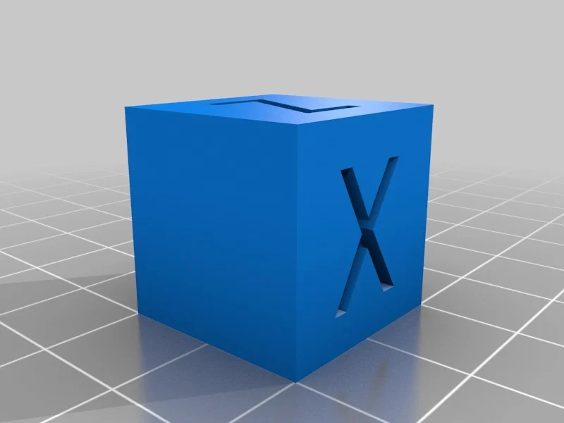
Step 1: Print a Calibration Cube
Design or download a 20 mm calibration cube. Measure all three dimensions using a digital caliper.
Step 2: Measure and Adjust
If your cube prints at 20.3 mm in X and 19.7 mm in Y, your printer is over-extruding in X and under-extruding in Y. Calculate the new steps-per-mm using this formula:
New steps/mm = (Expected dimension / Measured dimension) x Current steps/mm
Update your firmware or printer settings and reprint the cube. Repeat the process until your prints match your CAD model dimensions within ±0.1 mm.
Step 3: Z-Axis and Layer Height
Z-axis calibration is often overlooked but critical. A 10 mm tall part that prints at 9.8 mm may indicate a bed leveling or stepper motor issue. Ensure your build plate is level, and confirm that your Z-steps-per-mm are accurate.
Material Shrinkage and Thermal Expansion
Different materials behave differently when cooling. PLA has minimal shrinkage, while ABS and Nylon shrink significantly, leading to warping and undersized parts if unaccounted for.
Material | Approx. Shrinkage (%) | Notes |
PLA | 0.2% - 0.5% | Easy to print, stable |
PETG | 0.3% - 0.6% | Slight warping, good dimensional stability |
ABS | 0.7% - 1.2% | High shrinkage, requires enclosed chamber |
ASA | 0.8% - 1.0% | UV resistant, warps less than ABS |
Nylon | 1.5% - 2.0% | High shrinkage, requires drying and enclosure |
Compensating in CAD
To account for shrinkage:
Determine average shrinkage rate from test prints.
Scale the model in your CAD software accordingly. For example, for 1% shrinkage, scale up by 1.01.
Use slicer compensation settings if available (e.g., horizontal expansion or dimensional adjustments).
Understanding GD&T and Fitment in 3D Printing
Geometric Dimensioning and Tolerancing (GD&T) is a standardized method for communicating how a part should be manufactured and inspected. While 3D printing often doesn't meet traditional machining tolerances, adopting GD&T concepts can improve part fit and repeatability.
Hole and Shaft Fits
Clearance, transition, and interference fits are defined by the relationship between hole and shaft sizes.
Fit Type | Description | Application |
Clearance Fit | Always has space between parts | Snap-together parts |
Transition Fit | May have slight interference | Press-fit or tight slides |
Interference Fit | Always requires force to join | Permanent assemblies |

For 3D printing, consider the following adjustments (Note, always perform test prints to verify these values. Every printer prints differently):
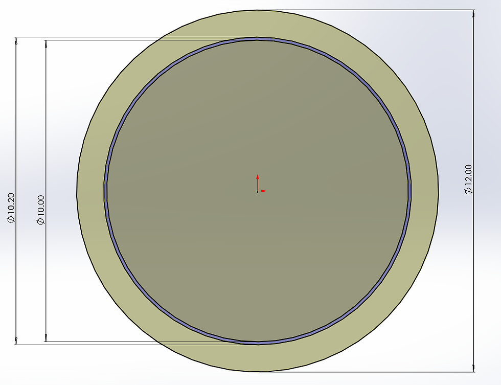
PLA: 0.2 - 0.3 mm clearance for moving parts
PETG: 0.3 - 0.5 mm clearance
ABS/ASA: 0.4 - 0.6 mm due to greater shrinkage
Nylon: 0.6 mm or more
Designing with Tolerances
Use test fitment prints before committing to production.
Chamfer or round edges where parts must slide together.
Avoid zero-clearance fits unless you post-process or sand parts.
Apply GD&T when parts need positional or profile accuracy, especially in mechanical assemblies.
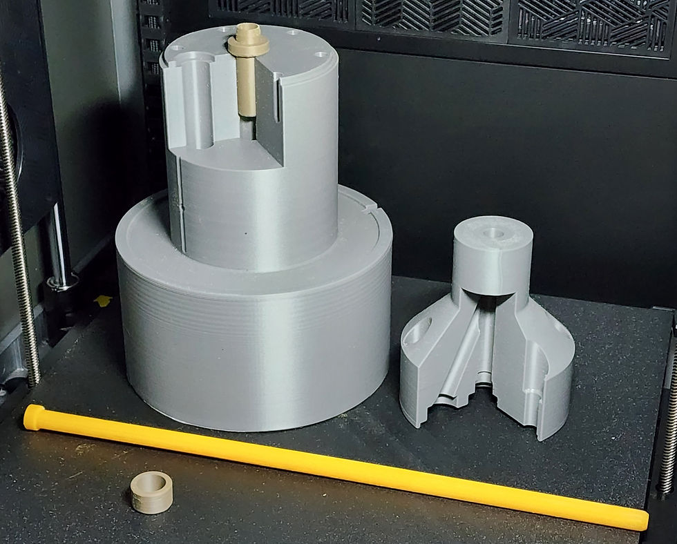
Post-Processing with Traditional Machining for Tight Tolerances
For applications where even ±0.1 mm isn’t accurate enough, traditional machining processes can be used to bring 3D printed parts into tighter dimensional tolerance bands. This is especially useful when producing jigs, fixtures, or functional assemblies where precise fit or alignment is critical.
Machining Methods Commonly Used on 3D Printed Parts
Drilling and Reaming: For precise holes and press-fit features, 3D printing undersized pilot holes followed by reaming can produce exact diameters.
Milling and Facing: Machining flat surfaces after printing helps eliminate layer inconsistencies and ensures perpendicularity or flatness.
Tapping and Thread Milling: Internal threads can be machined rather than printed to improve strength and accuracy.
Boring: For large-diameter holes requiring tight tolerances, boring out printed stock allows for excellent concentricity and finish.
Surface Grinding: Used occasionally for small, flat components when very fine surface finishes or tight thickness tolerances are required.

Preparing for Machining in Your Print
To ensure successful post-processing, your part should be printed with machining allowances. This includes:
Extra Wall Thickness: Add at least 1–2 mm of material where machining will occur to allow proper cleanup without compromising strength.
Reinforced Mounting Areas: Add boss features or sacrificial flanges to help fixture the part securely during machining.
Material Considerations: Choose filaments like carbon-fiber-reinforced nylon or higher temperature materials to increase machinability.
Adjusting Your Slicer Settings
In the slicer:
Increase the number of perimeters (walls) in regions you plan to machine—typically 4–6 walls are recommended.
Use 100% infill in machined zones for better tool engagement and to avoid delamination.
Disable adaptive layer height in areas requiring precise machining stock.
By planning your design and print for post-processing, you can unlock the benefits of both additive and subtractive manufacturing: speed and design freedom from 3D printing, and accuracy and surface finish from traditional machining.
Real-World Applications of Dimensional Accuracy
Industries from aerospace to automotive demand tight tolerances and predictable fitments. Dimensionally accurate 3D printing enables:
Replacement parts for machinery
Functional enclosures for electronics
Prototypes for tolerance-sensitive assemblies
Michigan Prototyping Solutions regularly uses X/Y calibration cubes and filament-specific scaling factors to deliver parts that match CAD specs within ±0.1 mm. For critical fits, we use test coupons, adjust CAD models, and tune extrusion flow rates.
Conclusion: A Blueprint for Dimensional Accuracy
Dimensionally accurate 3D printing isn’t guesswork—it’s a process. With proper calibration, a solid understanding of thermal expansion, and thoughtful CAD design using tolerancing principles, you can create reliable, functional parts that fit and perform as expected. Whether you're printing gears, jigs, or housing components, understanding 3D print tolerancing and 3D print fitments sets the foundation for successful builds.
Michigan Prototyping Solutions specializes in helping clients achieve precision results through calibrated machines and engineering-grade materials. If you need dimensionally accurate prints with a professional finish, we’re here to help.
Comentarios